The response of the cantilever to inputs plays an critical role in the operation of the Dimension Icon SPM in TappingMode. There is an important trade-off between the response time of the cantilever and the force applied to the sample. The cantilever does not respond instantly to perturbations in oscillation amplitude. The cantilever drive system pumps energy gradually into the cantilever oscillation.
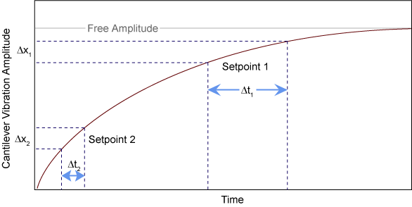
To demonstrate the conflicting requirements, figure 1 illustrates a typical response curve of the cantilever amplitude as a function of time, with the performance of the system analyzed at two operating points: Setpoint 1 and Setpoint 2.
Figure 1: Cantilever Response Curve
Setpoint 1 is only slightly lower than the free oscillation amplitude. This has the advantage of dissipating very little energy to the sample surface. The disadvantage is that the system takes longer to recover from a given perturbation in the amplitude. For example, consider the situation where the tip travels off a step with a height of Δx. At Setpoint 1 it takes longer for the amplitude of the cantilever oscillation to increase; therefore, the feedback system is slow (Δt1) responding to the error created by going off of the step (Δx1). At operating Setpoint 2 the cantilever amplitude builds up more rapidly. The feedback system senses the error caused by going off of the same size step (Δx2) and responds more rapidly (Δt2). However, more energy transfers to the sample surface while scanning with this setpoint .
.
The nature of the sample also influences the choice between faster response time versus lower contact force. For example, harder samples can withstand higher contact forces, so it is beneficial to improve the response time by lowering the Amplitude Setpoint. Soft samples that are relatively flat should run with higher Amplitude Setpoint values to reduce the energy imparted to the sample. In general, the solution to the problem is to decrease the scan rate and increase the feedback gains. In some situations, the feedback gains cannot increase without causing piezo oscillations; in such cases there is no choice but to reduce the scan rate.
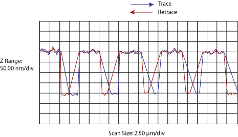
Inadequate response time typically occurs when the tip encounters a low point in the sample. The amplitude of the cantilever oscillation decreases very quickly when taller portions of the sample are encountered. As a result, the system response is markedly different depending on whether the tip is climbing or descending a feature in the sample. For this reason, viewing the Scope trace (below the scan) is very useful when setting scan parameters. As the tip descends, features are evaluated by comparing the Trace and Retrace. The image below illustrates the effects of poorly selected scan parameters on data obtained from a calibration standard with a series of sharp-walled pits. Regardless of the scan direction, the tip does not track the wall of the pit when the tip enters a pit. However, it does track the surface closely when moving out of the pit:
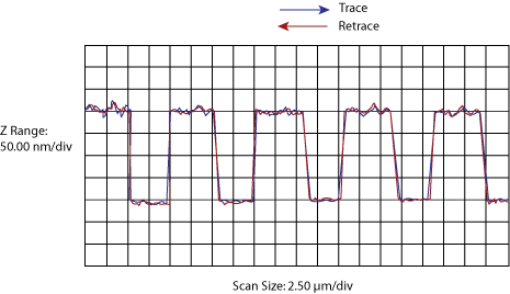
With a slight increase in the integral gain and a twofold decrease in the Scan Rate, the tip now tracks the surface when it descends into the pit as well as when it exits. The Trace and Retrace lines now coincide closely:
The Ease of Use Interface automatically sets certain parameters to optimize image quality.
| www.bruker.com | Bruker Corporation |
| www.brukerafmprobes.com | 112 Robin Hill Rd. |
| nanoscaleworld.bruker-axs.com/nanoscaleworld/ | Santa Barbara, CA 93117 |
| Customer Support: (800) 873-9750 | |
| Copyright 2010, 2011. All Rights Reserved. |
 Related Topics